TL;DR
A cable tray run is a system of straight lengths joined by fittings. The straight tray carries cable along a wall or ceiling; every change of direction, every branch, and every change of width is a purpose-made fitting bolted in with a jointing set. Cut and bend the straight tray on site and you lose the bend radius, the load behaviour, and the finish — the fitting exists so you don’t have to.
Metosu makes the full fitting set in the same TRC perforated / TRU non-perforated tray, in the same HDG and Jotun powder-coat finishes as the straight lengths. This walks one run from a switchroom, up a riser, around two corners, into a branch, and down in width — naming the fitting for each move.
| Fitting | Geometry it handles | When to use it |
|---|---|---|
| Inside riser | Vertical-to-horizontal transition, tray turning into the wall | Run leaves a riser and breaks out across a ceiling |
| Outside riser | Vertical-to-horizontal transition, tray turning away from the wall | Run climbs off a horizontal level up a riser face |
| Flat-wise elbow | Horizontal turn in the plane of the tray | Run changes direction along a flat ceiling or floor |
| Flat-wise cross | Four-way horizontal intersection | Two runs cross and exchange cables |
| Equal tee | Three-way branch, branch = main width | Full-width spur off the main run |
| Unequal tee | Three-way branch, branch < main width | Smaller spur feeding fewer cables |
| Straight reducer | Symmetric width change, centreline held | Width drops as cable count falls, centreline kept |
| Left/right-hand reducer | Offset width change, one side held | Width drops but one edge must stay aligned to a wall |
Why fittings, not field-cut tray
It is tempting to treat a corner as something the installer solves with an angle grinder and a folding tool. It is the wrong instinct. A factory fitting gives you three things a field cut cannot:
- A controlled bend radius. Cables have a minimum bend radius below which the insulation is stressed and, for data and fibre, performance degrades. A fitting holds the cable to a sweep, not a hard fold over a cut edge.
- Continuous load behaviour. A fitting is formed and reinforced to carry across the turn. A run nicked and bent on site has lost section exactly where the geometry concentrates stress.
- An intact finish. A HDG or powder-coat fitting arrives sealed on every edge. A site cut exposes bare steel that has to be cold-galvanised by hand and rarely matches.
So the rule is simple: the tray goes straight, and the fittings do every turn, branch, and width change. The rest of this article is which fitting for which move.
The run: from switchroom to load
Picture a single run leaving a switchroom. It will climb a riser, break out onto a ceiling, turn two corners, drop a branch to a sub-distribution board, and narrow as the cables peel off. Five fittings, in order.
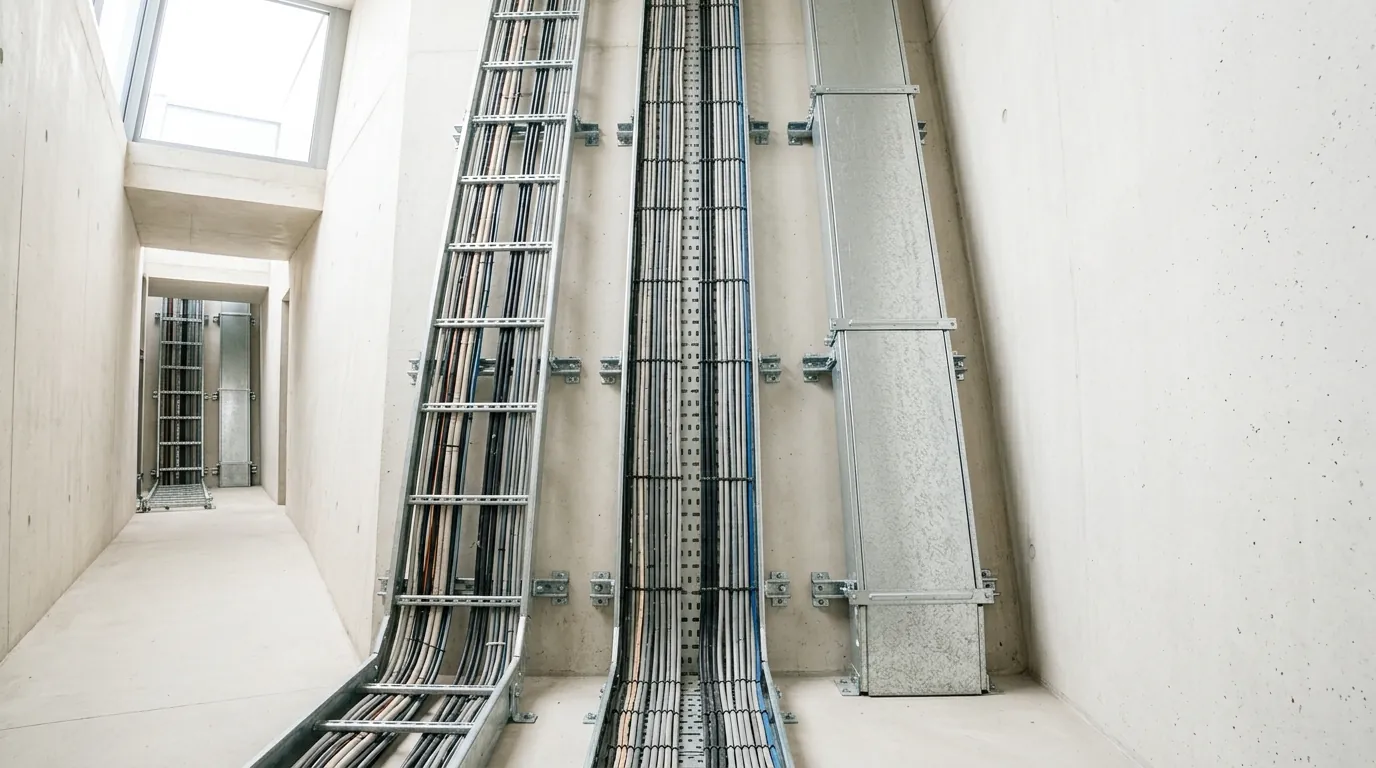
1. Up the riser — inside vs outside riser
The run leaves the switchroom horizontally, then has to turn vertically to climb the riser shaft, then turn horizontally again at the floor above. Each of those is a vertical-to-horizontal transition, and the riser fitting is what makes it.
The choice between inside riser and outside riser is about which face of the bend the cables sit on:
- An inside riser turns the tray into the wall — the cables run on the inside of the bend, the concave face. Use it where the run leaves a vertical riser and breaks into a horizontal level, hugging the structure.
- An outside riser turns the tray away from the wall — the cables run on the outside of the bend, the convex face. Use it where the run climbs off a horizontal level and onto the riser face.
The decision rule: stand at the bend and ask which side the cable load wants to fall toward. The riser is chosen so the tray base supports the cables through the turn rather than letting them sag off the edge. Get the inside/outside call wrong and the cables fight the fitting instead of resting in it.
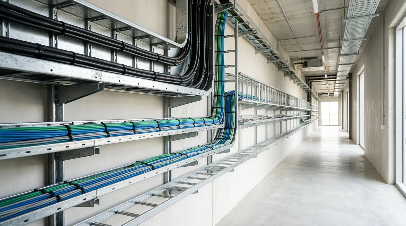
2. Onto the ceiling, around the corner — flat-wise elbow
At the top of the riser the run is now horizontal, travelling across a ceiling. The first corner is a turn in the plane of the tray — the tray stays flat, the direction changes left or right. That is a flat-wise elbow.
A flat-wise elbow is the workhorse of any horizontal run. It holds the cable to a sweep around the corner rather than a folded edge. Place a support close to the elbow on both sides: a fitting is a discontinuity, and the clean span behaviour of the straight run does not carry across it — the same reason support spacing tightens at every bend and fitting.
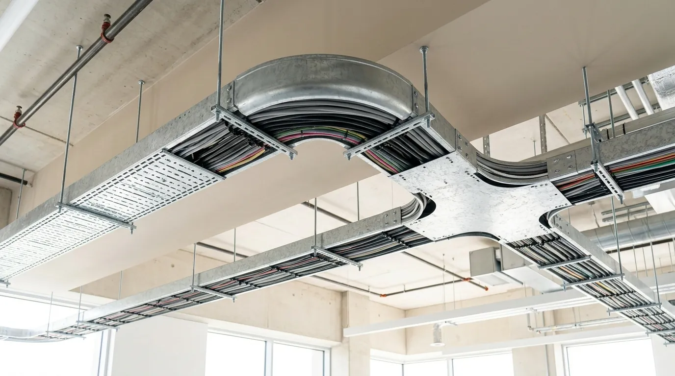
3. Where two runs meet — flat-wise cross
Further along, this run crosses a second run coming from another part of the building, and cables need to pass between them. A four-way horizontal intersection is a flat-wise cross. Use the cross only where you genuinely have four legs meeting and exchanging cable. Where one run simply passes over another with no interchange, you do not need a cross at all — you need vertical separation and, if power and data are involved, proper segregation between the layers.
4. Branching to a load — equal vs unequal tee
Now the run has to drop a spur to a sub-distribution board off to one side. A three-way branch is a tee, and the choice is about the width of the branch:
- An equal tee branches at the same width as the main run. Use it when the spur carries a full-width bundle — a major feeder splitting toward a large load.
- An unequal tee branches at a smaller width than the main. Use it when the spur feeds fewer cables — a sub-board, a lighting panel, a single piece of plant.
The decision rule is the cable count on the branch, not on the main. Size the tee branch to the cables it will actually carry, with the same spare allowance you gave the main run. An unequal tee on a lightly loaded spur saves steel and weight without starving the branch.
5. Narrowing the run — straight, left-hand, right-hand reducer
Past the branch, the main run is carrying fewer cables — some peeled off at the tee. A run that started at, say, 600 mm no longer needs that width. A reducer drops the tray from a wider section to a narrower one. All Metosu reducers are 100 mm height, so the reduction is purely in width, not depth — the cables stay at the same level through the change.
Three reducers cover the three geometries:
- A straight reducer holds the centreline and narrows symmetrically from both edges. Use it on a run routed down the middle of a space, where both edges can move in equally.
- A left-hand reducer holds the left edge and narrows from the right. Use it where the left edge must stay aligned — flush to a wall, a beam, or the run it shares a support with.
- A right-hand reducer holds the right edge and narrows from the left. The mirror case: the right edge is the one that has to stay put.
The decision rule: identify which edge of the run is the fixed reference on site. If it is the centreline, use a straight reducer. If it is an edge against the structure, use the hand that keeps that edge continuous. Reducing on the wrong hand throws the run off its reference line and forces a kink the cables then have to negotiate.
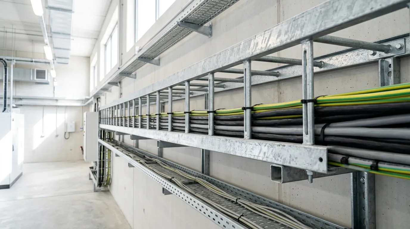
The accessories that hold it together
The fittings turn and branch the run; the accessories fix it, join it, close it, and keep the cables sorted:
- Hangers and brackets carry the tray off the structure — the support points whose spacing decides whether the load rating still holds.
- Jointing sets splice one length or fitting to the next. Every joint is also an electrical interface: a tray run is only continuous as an earth path if the joints are bonded, which is why earthing and bonding across fittings and joints is a design item, not an assumption.
- Clamps secure the tray to its supports and secure cables within the tray.
- End plates close off the cut end of a run so cables are not exposed at a raw edge.
- Separators run along the tray to divide power from data, or one circuit group from another, inside a shared tray.
Reading the part code
Metosu fittings follow the same code logic as the straight tray. The base code identifies the perforated line, -SLW; for the non-perforated variant of the same fitting, substitute -SLU for -SLW in the part code. The fitting type, width, and finish then read off the rest of the code the same way they do on a straight length. One consequence worth stating: a perforated tray run and its fittings should be specified as the perforated line throughout — don’t mix a -SLW tray with -SLU fittings and expect them to match on finish or perforation.
Bend radius and cable protection
The geometry is only half the job. The fitting also has to protect the cable through the turn:
- Respect the cable’s minimum bend radius. The fitting sweeps the cable; never let a field modification tighten that sweep below the cable manufacturer’s minimum — it is the single most common way insulation and data performance are quietly lost at a corner.
- Support the fitting on both sides. Treat every elbow, tee, cross, and reducer as a point that needs a support close to it. Don’t span a fitting between two distant brackets.
- Keep the finish intact. Use factory fittings rather than site cuts so the HDG or 60–80 µm Jotun powder-coat finish stays continuous — fittings ship in the same finishes as the straight tray for exactly this reason.
- Bond across every joint. A jointing set is a mechanical splice, not automatically an electrical one. Where the tray is part of the earth path, bond across each fitting and joint.
For heavier feeders, long vertical drops, or where the cables are large and the bend radius is generous, the same routing logic applies to cable ladder, which carries the same fitting families at ladder widths.
Specifying the fittings
When you write fittings into a BOQ, specify them as deliberately as the straight tray:
- Call out each fitting type by geometry — riser (inside/outside), flat-wise elbow, flat-wise cross, equal/unequal tee, reducer (straight/left/right) — not just “fittings as required”.
- State the finish to match the straight run — HDG to ISO 1461, or Jotun powder coat at 60–80 µm to the relevant ISO 12944 class.
- Require jointing sets, end plates, and separators as named line items, not assumed inclusions.
- Note where bonding across joints is required so the earth continuity is priced and installed, not left to chance.
A run specified this way arrives as a kit that bolts together to the drawing. A run specified as “tray and fittings to suit” arrives as straight lengths and an angle grinder.
Talk to us about your run
Send the routing — the riser transitions, the corners, the branches, and where the width steps down — and Metosu can specify the fitting set, finish, and accessories to match. Email [email protected] or contact the Metosu technical team.
Further reading
- Cable tray support spacing — why spacing tightens at every fitting
- Cable tray earthing and bonding — keeping the earth path continuous across joints and fittings
- Cable tray · Cable ladder · Full catalogue (PDF)